Hopefully you have already looks at some of the "beginner" level Processing tutorials, such as:
- Hello Processing
- Getting Started
- Processing Overview
- Coordinate Systems and Shapes
- Color
- Trig Primer or this site's Sines, Cosines and All That.
You need to have worked through at least these tutorials to understand what follows, because I will be using techniques from each of them.
The first step in writing any program is to have a clear idea of what you want to achieve. If you do not have any idea of where you want to end up, you are very unlikely to get there. (OK! So journeys in art are often as much about exploration as following a well-defined route from A to B. The point is still valid: you need some initial ideas about where you might find interesting landscapes.)
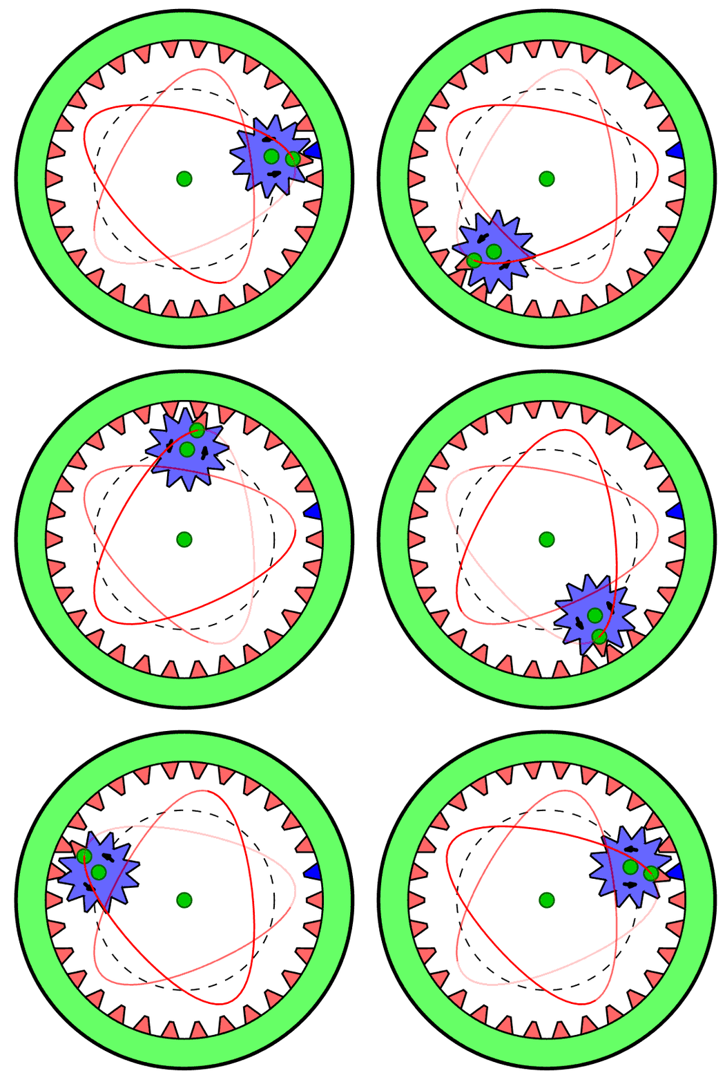
This project is inspired by memories of a childhood toy - the "Spirograph" (see the Wikipedia entry) which produced designs such as these:


Spirograph was made with plastic gear wheels. By choosing various gear ratios and pen colours one could make a wide variety of figures featuring harmonic motions. (The figure on the right was copied from the Wikipedia page.) Interestingly, Spirograph is still available on the market today, so it still generates visual interest with young people.
Can we reproduce the figures generated by Spirograph using a computer program? (Obviously we can, but how?) This will provide us with a first project to explore how Processing can be used to work our way towards a definite visual goal.
In fact, it will soon become obvious that Processing allows us to go way beyond what was possible with Spirograph. We can, for example, make changing the gear ratios interactive, so we see immediately the effect of different choices. If we wish, we can also make some of the basic parameters vary with time. For example, we can gradually reduce the size of the gears, or we can blend colours rather than switching pens, or we can use nibs with more interesting shapes than a simple point.
Where do we start? We will certainly need to know how to draw a circle. If you have followed the Processing basic level tutorials, you will now know that you can draw a circle using the command such as ellipse(200,200,100,100);. (Reminder: this command says make the (x,y) position (200,200) the center of the figure and make the width and height (200,200), so this produces a circle of radius 100 pixels centred on a point 200 pixels from the left of the window and 200 pixels from the top.)
However, this will not do the trick for us. We need to make small circles run round the inside of big circles, so we are going to need to make them a step at a time as we rotate round the diagram. So, the first thing we need to do is learn how to draw a regular polygon, with a specified number of sides, and we will eventually make the number of side so big that we can no longer see the difference from a proper circle.
float r0 = 150.0;             // The radius of our circle in pixels.

int   nsides = 12;            // The number of side in our regular polygon.
float ith    = TWO_PI/nsides; // Increment in angle for each side of the figure.

int x0 = 200;                 // The centre of the polygon - x coordinate.
int y0 = 200;                 // The centre of the polygon - y coordinate.

void setup()                  // Executed once when Processing starts-up.
{
  size(400,400);              // Size of our canvas.
  background(100);            // Make the background colour grey.
  stroke(255,255,255);            // Draw the outline in white.
}

void draw()
{

  for(int i=0;i<nsides;i++)   // Draw a line for each side
    {
      float theta = i*ith;                  // Increment the angle each time round the loop.
      int x1 = x0 + int(r0*cos(theta));     // x position of start of each line.
      int y1 = x0 + int(r0*sin(theta));     // y position of start of each line.
      int x2 = x0 + int(r0*cos(theta+ith)); // x position of end of each line.
      int y2 = x0 + int(r0*sin(theta+ith)); // y position of end of each line.
      line( x1,y1, x2,y2);                  // draw the line.
    }
}
|
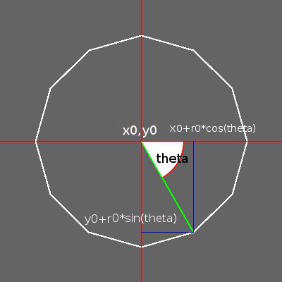
This is the figure (in white) produced by the above program. (The coloured lines and annotations are a later addition, to aid explanation.) Already this simple program introduces a number of important points that need further comment.
|
 |
So, we now have a method of drawing a polygon that can look as close as we like to a circle. We draw it by allowing the value of theta to go from 0 to 2*π radians. We are going to call this our first harmonic, for reasons that will become clear later.
Things only really start to get interesting when we introduce epicycles that correspond to the smaller gears in Spirograph. We could arrange for another circle to effectively roll around the inside of our first harmonic circle, but this introduces a bit of programming clutter that we do not really need. We can get exactly the same visual effects letting its center move along the circumference of our first-harmonic circle, but rotating from 0 to 2*π twice while we go round the first harmonic once. This is our second harmonic, and we will want to choose its radius to be anything we like. We carry on doing the same thing for third, forth, fifth harmonics and so on, each rotation going 3, 4 or 5 times as fast respectively. We will stop at the ninth for the time being - that is sufficiently complicated already. The program and some of the results are shown in the next page.
